Mazda 6 Service Manual: Manual transaxle removal/installation
1. Remove the battery, battery tray and battery bracket.
2. Remove the air cleaner compornent. (See INTAKE-AIR SYSTEM REMOVAL/INSTALLATION.)
3. Remove the wheels, tires and splash shields.
4. Remove the under cover.
5. Remove the steering gear and power steering pipe. (See STEERING GEAR AND LINKAGE REMOVAL/INSTALLATION.)
6. Remove the front auto leveling sensor. (See FRONT AUTO LEVELING SENSOR REMOVAL/INSTALLATION.)
7. Drain the transaxle oil into a suitable container.
8. Remove in the order indicated in the table.
9. Install in the reverse order of removal.
10. Adjust the headlight zeroset. (See HEADLIGHT ZEROSET.)
11. Add the specified amount of specified transaxle oil.
12. Install the air cleaner compornent. (See INTAKE-AIR SYSTEM REMOVAL/INSTALLATION.)
13. Warm up the engine and transaxle, inspect for oil leakage, and inspect the transaxle operation.

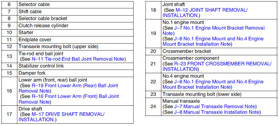
No.1 Engine Mount Bracket Removal Note
1. Support the engine using the SST before removing the No.1 engine mount.
2. Remove the No.1 engine mount.
Manual Transaxle Removal Note
1. Loosen the SST
(49 E017 5A0)and lean the engine toward the transaxle.
2. Support the transaxle on a jack.
3. Remove the transaxle mounting bolts.
4. Remove the transaxle.
Manual Transaxle Installation Note
1. Set the transaxle on a jack and lift into place.
2. Install the transaxle mounting bolts.
3. Tighten the SST
(49 E017 5A0)so that the engine is located at the specified position.
No.1 Engine Mount and No.4 Engine Mount Bracket Installation Note
1. Verify that the engine mount rubbers are installed as shown.
2. By aligning the holes with the stud bolts, install the No.4 engine mount bracket to the transaxle.
3. By aligning the holes with the stud bolts, install the No.1 engine mount to the transaxle.
4. Align the hole of the No.4 engine mount bracket with the No.4 engine mount rubber on vehicle, and temporarily tighten the bolt D.
5. Tighten the nut B,C in order of B→C, then bolt A.
6. Tighten the bolt D.
Tightening torque A, B, C: 66.6-93.1 N·m {6.8-9.4 kgf·m, 50-68 ft·lbf} D: 85.3-116.6 N·m {8.7-11.8 kgf·m, 63-85 ft·lbf}
7. Tighten the bolt D to the No.1 engine mount.
Tightening torque E: 85.3-116.6 N·m {8.7-11.8 kgf·m, 63-85 ft·lbf}
8. Remove the SST
(49 E017 5A0).
 Vehicle speedometer sensor inspection
Without ABS
1. Remove the vehicle speedometer sensor.
2. Measure voltage (AC range) between terminals of the vehicle speedometer
sensor while the gear is turning.
3. Install the vehicle speed ...
 Shift mechanism
1. Remove the battery, battery tray and battery bracket.
2. Remove the air cleaner component. (See INTAKE-AIR SYSTEM
REMOVAL/INSTALLATION.)
3. Remove the dashboard compleat. (See DASHBOARD REMOVAL ...
Other materials:
Mazda 6 Service Manual: Base installation
1. Cut away all of the original sealant using a razor.
2. Clean and degrease the ceramic coating on the glass and the base.
3. Apply primer to the bonding area of the glass and the base.
Caution
Keep the area free of dirt and grease, and do not touch the
surface or the primer may not prope ...
Mazda 6 Service Manual: Rear beltline molding removal
Note
When removing the rear beltline molding, the clip may be damaged.
If the clip is damaged, replace it with a new one.
1. Pull the A section upward and remove the clip.
2. Rotate the B section of the front beltline molding in direction (2), along
the direction (1) shown in the figu ...