Mazda 6 Service Manual: Panel light control switch inspection
1. Connect the connector to the panel light control switch.
2. Connect the negative battery cable.
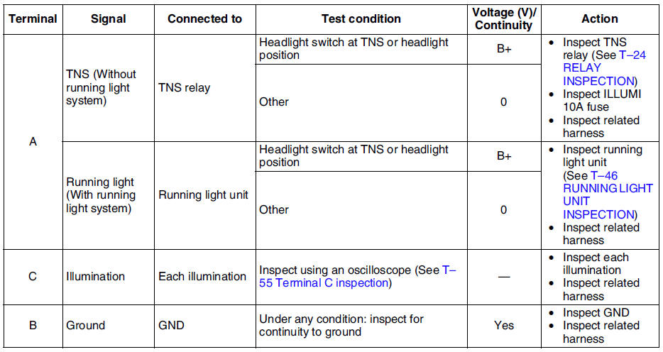
3. Measure the voltage at the panel light control switch using voltmeter.
- When inspecting terminal B for continuity, disconnect the panel light control switch connector.
4. If the value are not as specified in the Terminal Voltage List (Reference), inspect the parts under Action and related wiring harnesses.
5. If the system does not work properly even though the parts or related wiring harnesses do not have any malfunction, replace the panel light control switch.
Terminal Voltage Table (Reference)


Terminal C inspection
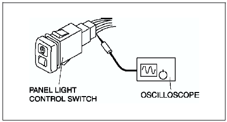
1. Measure the wave pattern of the terminal C on the panel light control switch using an oscilloscope.

2. Set the headlight switch to either the TNS or headlight position.
3. Set the panel light control switch to the brightest position.
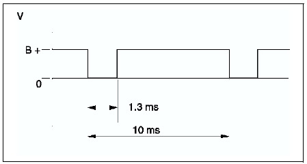
4. Verify that the pattern on the screen is as shown in the figure.

5. Verify that the pattern on the screen matches the pattern shown in the figure as the panel light control switch is gradually turned to the darkest position.

 Panel light control switch removal/installation
1. Disconnect the negative battery cable.
2. Remove in the order indicated in the table.
3. Install in the reverse order of removal.
Panel Light Control Switch Removal Note
1. Insert your hand ...
 Wiper and washer
...
Other materials:
Mazda 6 Service Manual: General procedures
PRECAUTION (BRAKES)
Wheels and Tires Removal/Installation
1. The removal and installation procedures for the wheels and tires are not
mentioned in this section. When a
wheel is removed, tighten it to 88-118 N·m {9.0-12.0 kgf·m, 65.0-87.0 ft·lbf}.
Brake Lines Disconnection/Connection
Cautio ...
Mazda 6 Service Manual: Locking, Unlocking with Request Switch, Door Handle (With the advanced keyless
function)
All doors can be locked/unlocked by pressing the request switch on the front
doors while the key is being carried.
Front doors
To lock
To lock the doors , press the request switch and the hazard warning lights will
flash once.
A beep sound will be heard once.
To unlock
Driver's door requ ...
