Mazda 6 Service Manual: Abs (abs/tcs) hu/cm inspection
1. Disconnect the negative battery cable.
2. Connect the SST
between the ABS (ABS/TCS) HU/CM and harness connector with the ignition switch off.
3. Attach the tester leads to the SST
and inspect voltage referring the table below.
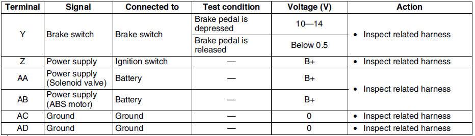
Terminal Voltage Table (Reference)
(Engine is idling, and connector is connected unless otherwise indicated.)
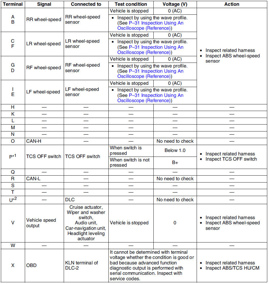
*1 : With TCS
*2 : Use this terminal at factory only, not used for inspection and repair at field
Inspection Using An Oscilloscope (Reference)
Wheel speed
- ABS/TCS HU/CM terminal:
RR : A ( + ) - B ( - )
LR : C ( + ) - F ( - )
RF : D ( + ) - G ( - )
LF : E ( + ) - I ( - )
- Oscilloscope setting:
1 V/DIV (Y), 2 ms/DIV (X), AC range
- Vehicle condition: Driving 30 km/h (18.6 mph)
Note
- As vehicle speed increases, period of wave shortens.
- If there is malfunctioning in the sensor rotor, wave profile warps.
Vehicle speed output
- ABS/TCS HU/CM terminal: V( + ) - AC ( - )
- Oscilloscope setting:
1 V/DIV (Y), 5 ms/DIV (X), DC range
- Vehicle condition: Driving 30 km/h (18.6 mph)
Note
- As vehicle speed increases, period of wave shortens.
 Abs (abs/tcs) or dsc hu/cm configuration
1. Connect the WDS or equivalent to the DLC-2.
2. Input vehicle information following the direction on the WDS or equivalent
screen.
3. Select Module programming.
4. Select Programmable module ...
 Tcs (dsc) off switch removal/installation
1. Press the hooks of the TCS OFF switch and pull the switch out.
2. Disconnect the connector.
3. Install in the reverse order of removal. ...
Other materials:
Mazda 6 Service Manual: Sunroof unit removal/installation
1. Disconnect the negative battery cable.
2. Remove the headliner.
3. Remove the glass panel.
4. Disconnect the front and rear drain hose from the sunroof frame.
5. Remove the bolt A, and then remove the rear set bracket.
6. Remove the bolt B and nuts, and then remove the sunroof unit.
7. In ...
Mazda 6 Service Manual: Spark plug removal/installation
1. Disconnect the negative battery cable.
2. Remove the plug hoie plate.
Lift off and remove the plug hole plate from the installation areas
(rubber and clips) as shown in the figure.
3. Disconnect the high-tension lead.
4. Remove the spark plugs using the plug-wrench.
5. Install th ...