Mazda 6 Service Manual: Pcm inspection
Note
- PIDs for the following parts are not available on this model. Go to the appropriate part inspection page.
- CMP sensor (See CAMSHAFT POSITION (CMP) SENSOR INSPECTION.)
- Main relay (See RELAY INSPECTION.)
1. Connect the SST
(WDS or equivalent) to the DLC-2.
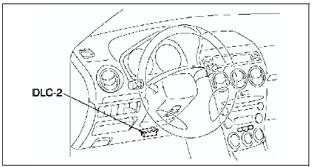
2. Turn the ignition switch to ON position.
3. Measure the PID value.
- If PID value is not within the specification, follow the instructions in Action column.
Note
- The PID/DATA MONITOR function monitors the calculated value of the input/output signals in the PCM. Therefore, an output device malfunction is not directly indicated as a malfunction of the monitored value for the output device. If a monitored value of an output device is out of specification, inspect the monitored value of the input device related to the output control.
- For input/output signals except those of the monitoring items, use a voltmeter to measure the PCM terminal voltage.
- The simulation items that are used in the ENGINE CONTROL SYSTEM OPERATION INSPECTION are as follows.
- ACCS
- ALTF
- EVAPCP
- FAN1
- FAN2
- FAN3
- FP
- HTR11
- HTR12
- IAC
- IASV
- IMRC
- IMTV
- VT DUTY1
PID/DATA monitor table (reference)
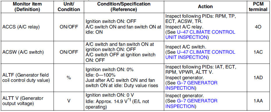
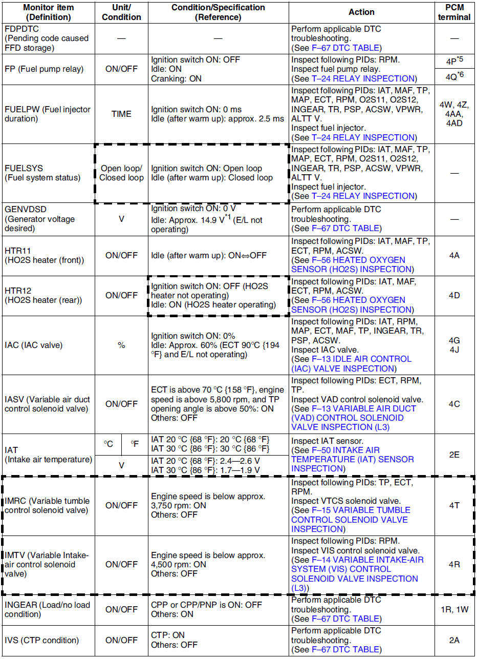
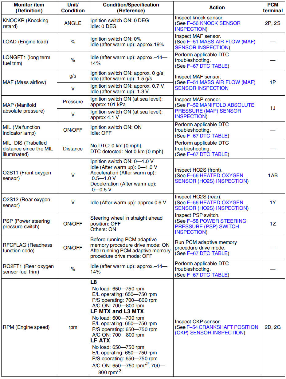
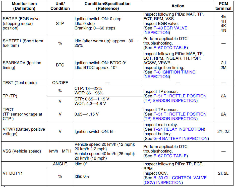
*1 : Calculated value; differs from terminal voltage
*2 : Refrigerant pressure switch (middle) turns on when the refrigerant pressure is 1.691.84 MPa {17.318.7 kgf/cm2, 247265 psi}
*3 : Refrigerant pressure switch (middle) turns off when the refrigerant pressure is 1.261.49 MPa {12.915.1 kgf/cm2, 184214 psi}
*4 : L3 and L8, LF (Intensely hot area) models
*5 : Immobilizer system equipped
*6 : Immobilizer system not equipped
- Following PIDs are for the ATX models. If inspects for following PIDs, see PID/DATA MONITOR INSPECTION.
PIDs for the ATX models
- GEAR
- LINEDES
- LPS
- OP_SW_B
- SSA/SS1
- SSB/SS2
- SSC/SS3
- TCS
- TFT
- TFTV
- THOP
- TR
- TR_SENS
- TSS
 Pcm removal/installation
Note
For replace the PCM, Setup the WDS and perform the PCM
configuration. (See PCM CONFIGURATION.)
1. Disconnect the negative battery cable.
2. For R.H.D, perform the following procedures. ...
 Pcm configuration
1. Connect the WDS to DLC-2.
2. Set up the WDS (including the vehicle recognition.)
3. Select Module programming.
4. Select Programmable module installation.
5. Select PCM and perform procedures ...
Other materials:
Mazda 6 Service Manual: Picture Quality Adjustment
WARNING
Always adjust the picture quality of the rear view monitor while the vehicle
is stopped: Do not adjust the picture quality of the rear view monitor while
driving the vehicle. Adjusting the picture quality of the rear view monitor such
as brightness, contrast, color, and tint while dri ...
Mazda 6 Service Manual: Lane-Change Signals and Three-Flash Turn Signal
Lane-Change Signals
Move the lever halfway toward the direction of the lane change—until the indicator
flashes— and hold it there. It will return to the off position when released.
Three-Flash Turn Signal
After releasing the turn signal lever, the turn signal indicator flashes three
times ...