Mazda 6 Service Manual: Rear crossmember removal/installation
Caution
- Performing the following procedures without first removing the ABS wheel-speed sensor may possibly cause an open circuit in the harness if it is pulled by mistake. Before performing the following procedures, remove the ABS wheel-speed sensor (axle side) and fix it to an appropriate place where the sensor will not be pulled by mistake while servicing the vehicle.
1. Remove the rear auto leveling sensor and harness. (See REAR AUTO LEVELING SENSOR REMOVAL/INSTALLATION.)
2. Remove the middle pipe. (See EXHAUST SYSTEM REMOVAL/INSTALLATION.)
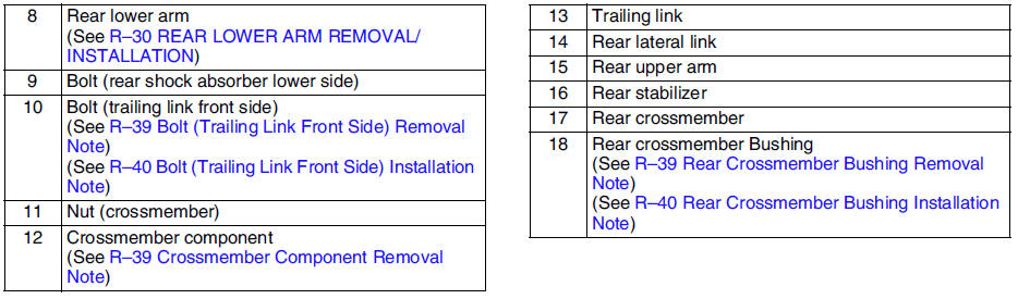
3. Remove in the order indicated in the table.
4. Install in the reverse order of removal.
5. Adjust the headlight zeroset. (See HEADLIGHT ZEROSET.)
6. Inspect the rear wheel alignment. (See REAR WHEEL ALIGNMENT.)
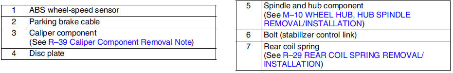
Caliper Component Removal Note
Remove the caliper, and suspend it aside with cable.
Bolt (Trailing Link Front Side) Removal Note
1. Support the trailing link with a jack.
2. Loosen the bolt (lateral link inner side).
Crossmember Component Removal Note
1. Support the crossmember component using a jack and remove the nuts.
Warning
- Removing the crossmember is dangerous. The crossmember component could fall and cause serious injury or death. Verify that the jack securely supports the crossmember component.
2. Remove the crossmember component.
Rear Crossmember Bushing Removal Note
Remove the bushing using screw driver (-), being care not to damage the rear crossmember.
Rear Crossmember Bushing Installation Note
1. Set the bushings as shown in the figure.
2. Tap the bushing onto the rear crossmember using the SSTs
.
Bolt (Trailing Link Front Side) Installation Note
1. Support the trailing link with a jack.
2. Tighten the bolts (trailing link front side).
 Trailing link removal/installation
Caution
Performing the following procedures without first removing the ABS
wheel-speed sensor may possibly cause an open circuit in the harness if it
is pulled by mistake. Before performing ...
 Body
Body
...
Other materials:
Mazda 6 Service Manual: Clutch cover inspection
1. Measure the wear of the diaphragm spring fingers.
If not as specified, replace the clutch cover.
Depth
0.6 mm {0.024 in} max.
2. Measure the flatness of the pressure plate with a straight edge and a
feeler gauge.
If not as specified, replace the clutch cover.
Maximum ...
Mazda 6 Service Manual: Plastic Part Maintenance
When cleaning the plastic lenses of the lights, do not use gasoline, kerosene,
rectified spirit, paint, thinner, highly acidic detergents, or strongly alkaline
detergents. Otherwise, these chemical agents can discolor or damage the surfaces
resulting in a significant loss in functionalit ...