Mazda 6 Service Manual: Wheel hub, steering knuckle removal/installation
Caution
- Performing the following procedures without first removing the ABS wheel-speed sensor may possibly cause an open circuit in the harness if it is pulled by mistake. Before performing the following procedures, remove the ABS wheel-speed sensor (axle side) and fix it to an appropriate place where the sensor will not be pulled by mistake while the vehicle is being serviced.
1. Remove in the order indicated in the table.
2. Install in the reverse order of removal.
3. After installation, inspect the front wheel alignment. (See FRONT WHEEL ALIGNMENT.)
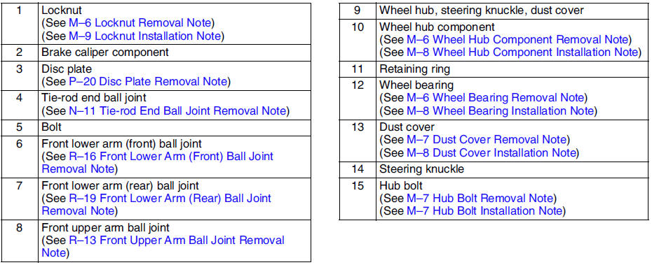
Locknut Removal Note
1. Knock the crimped portion of the locknut outward using a small chisel and a hammer.
2. Lock the hub by applying the brakes.
3. Remove the locknut.
Wheel Hub Component Removal Note
1. Remove the wheel hub component using the SSTs
.
2. If the bearing inner race remains on the front wheel hub component, grind a section of the bearing inner race until approx. 0.5 mm {0.02 in}
remains. Then remove it using a chisel.
Wheel Bearing Removal Note
Remove the wheel bearing using the SSTs
.
Dust Cover Removal Note
Note
- The dust cover does not need to be removed unless it is being replaced.
1. Mark the dust cover and steering knuckle for proper installation.
2. Remove the dust cover using a chisel.
Hub Bolt Removal Note
Note
- The hub bolts do not need to be removed unless they are being replaced.
Remove the hub bolts using a press.
Hub Bolt Installation Note
Install the new hub bolts using a press.
Dust Cover Installation Note
1. Mark the new dust cover in the same way as the removed one.
2. Align the marks of the new dust cover and the knuckle.
3. Install the new dust cover using the SSTs
.
Wheel Bearing Installation Note
Install the new wheel bearing using the SSTs
.
Wheel Hub Component Installation Note
Install the wheel hub component using the SSTs
.
Locknut Installation Note
Install a new locknut and stake it as shown.
 Wheel hub bolt replacement
1. Remove the hub bolt using the SSTs.
Note
If the dust cover interferes with the wheel hub bolt and the wheel
hub bolt cannot be removed, tap the part shown in the figure with a chisel
l ...
 Rear axle
...
Other materials:
Mazda 6 Service Manual: Winter Driving
Carry emergency gear, including tire chains, window scraper, flares, a small
shovel, jumper cables, and a small bag of sand or salt.
Ask an Authorized Mazda Dealer to check the following:
Have the proper ratio of antifreeze in the radiator.
Inspect the battery and its cables. Cold reduces b ...
Mazda 6 Service Manual: Using LATCH Lower Anchor
Your Mazda is equipped with LATCH lower anchors for attachment of specially designed
LATCH child-restraint systems in the rear seats. Both anchors must be used, otherwise
the seat will bounce around and put the child in danger. Most LATCH child-restraint
systems must also be used in conjunctio ...