Mazda 6 Service Manual: Front lower arm (front) removal/installation
1. Remove in the order indicated in the table.
2. Install in the reverse order of removal.
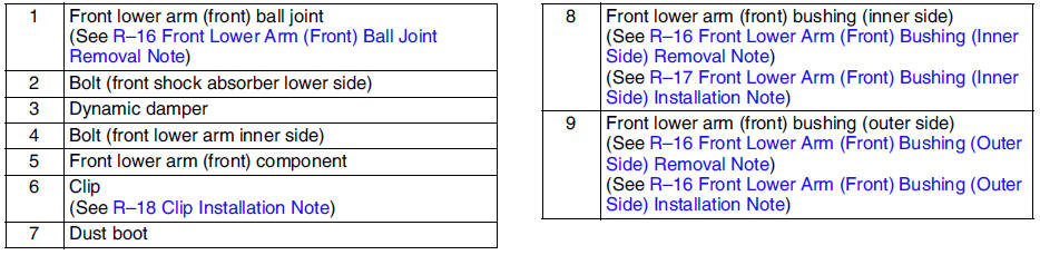
Front Lower Arm (Front) Ball Joint Removal Note
Separate the ball joint from the knuckle using the SSTs
.
Front Lower Arm (Front) Bushing (Inner Side) Removal Note
Press the bushing (inner side) out using the SSTs
.
Front Lower Arm (Front) Bushing (Outer Side) Removal Note
Press the bushing (outer side) out using the SSTs
.
Front Lower Arm (Front) Bushing (Outer Side) Installation Note
1. Mark the new bushing as shown in the figure.
2. Press the bushing in to the marking using the SSTs
.
3. Verify that clearance distance AB is 8.75 mm - 10.75 mm {0.3445 in - 0.4232 in}.
Front Lower Arm (Front) Bushing (Inner Side) Installation Note
1. Mark the new bushing as shown in the figure.

2. Press the bushing in to the marking using the SSTs
.
3. Verify that clearance distance AB is 12.75 mm - 14.75 mm {0.5020 in - 0.5807 in}.
Clip Installation Note
1. Wipe the grease off the ball stud.
2. Fill the inside of the new dust boot with grease.
3. Install the boot on the ball joint.
4. Install the new clip using the SST
.
5. Verify that the clip is installed securely to the groove.
6. Wipe away the excess grease.
 Front upper arm inspection
1. Remove the upper arm from the vehicle.
2. Inspect for damage, cracks, and bending.
3. Inspect the ball joint rotation torque.
(1) Rotate the ball joint five times.
(2) Measure the rotatio ...
 Front lower arm (front) inspection
1. Remove the lower arm (front) from the vehicle.
2. Inspect for damage, cracks, and bending.
3. Inspect the ball joint rotation torque.
(1) Rotate the ball joint five times.
(2) Measure the ...
Other materials:
Mazda 6 Service Manual: Interior Equipment (View A)
1 - Door-lock knob 2 - Lighting control 3 - Turn and lane-change signal
4 - Wiper and washer lever 5 - Tire pressure monitoring system set switch 6
- DSC OFF switch 7 - Lane-keep Assist System (LAS) & Lane Departure Warning System
(LDWS) OFF switch 8 - Outside mirror switch 9 - Door-lock ...
Mazda 6 Service Manual: Rear outer handle removal/installation
1. Remove the rear door glass.
2. Remove the rear door unit.
3. Remove the rear door latch.
4. Remove the bolts.
5. Detach the rear outer handle and rear door latch rod.
6. With the rear side of the rear outer handle fixed and the outer handle
lever pulled out (1), remove the rear side of t ...